 |
| 4'x4'x8'x grow tent with 8 COB LEDs installed. |
In this post, I'll try to explain the basics of how to match LEDs and drivers. I use chip-on-board (COB) LEDs as examples, but the principle applies to any LEDs. Here are links to my previous blog posts about DIY COB LEDs and linear LED modules. I'll cover the following topics:
- Basics
- Matching the LEDs with the driver
- Multiple LEDs driven by a single driver
- An example of my setup with 4x CXB3590
- Measurement of light coverage homogeneity
1. Basics
Types of drivers: Most LEDs require direct current (DC), so alternating current (AC) of the power outlet has to be converted to DC. This is one of the roles of LED drivers (power supplies). We usually use something called constant current (CC) drivers instead of more common constant voltage (CV) drivers. A CV driver is similar to a computer power supply, USB charger/outlet, or some of "wall bricks" used for some appliances. An USB outlet provides constant 5V, and depending on the load (resistance), the CV driver adjusts the current; it provides high current (within its capacity) for a low resistance load, or small amount of current for a high resistance load. From this aspect, it behaves similar to a battery. A CV driver can be used for LEDs, but it has several undesirable properties. With LEDs, as you increase the voltage, the current going through the LEDs increases. So the LED becomes brighter since the brightness is correlated with the current (somewhat linearly, but with a diminishing return). But the voltage-current relationship is approximately exponential (link to wikipedia). This means that a small differences in the voltage makes a huge difference in the current (and brightness). Due to manufacturing variations in CV drivers, a 5V CV driver might give 5.5V, and the LED might draw more current than what you intend to use. Sometime, it could over-shoot the maximum current capacity of the LEDs due to the voltage variation, and the LEDs might burn out (a bit exaggerated). Now, the cheap flexible LED strip lights, which you can cut into your own size, generally use 12V or 24V CV drivers. But they are inherently inefficient at this moment (partly due to their design). Therefore, it is insane to use these as grow lights which are turned on for 12-14 hours a day. Even if it is free, you'll end up paying more money for electricity within a year or two. Well, if the electricity is really cheap, or if you are rich (or if you don't care about wasting energy), they are surely convenient.
With a CC driver, the driver adjusts the voltage to maintain the constant current. They come in different current ratings (e.g. 500mA, 700mA, 1050mA, 1.4A) instead of voltage ratings such as 5V, 9V, 12V of CV drivers. So a 1.4A CC driver tries to adjust the voltage within its capacity (e.g., 9-42V) in order to provide the constant current of 1.4A. Another property of LEDs is that the relationship between voltage and current changes as the LEDs warm up, so the brightness can change after a couple minutes with a CV driver. Since the CC driver tries to maintain the constant current, the change in brightness due to the temperature becomes smaller with a CC driver than with a CV driver. Also, it is much easier to control the brightness because the driver is maintaining the constant current (remember that brightness is correlated with current?).
Efficiency of AC/DC conversion: Some energy is lost during the conversion of AC to DC, and different drivers could have different efficiencies. A good driver can achiev 94% efficiency, which means 6% of energy from AC input is wasted. Generally small wattage drivers seem to be less efficient, and the efficiency may be around 80%. Something close to 90% is the kind of efficiency you want to target.
Brands of CC drivers: There are many brands of CC drivers for LEDs. I have used cheap ones from China (via eBay) in the past as mentioned in my older DIY COB post. They perform well (decent efficiencies), and I have only 1 out of 10 or so drivers failed in the last 2-3 years. However, their rated current is rather approximate, so you don't know the current you'll get from a driver until you try it. I got a huge variation in the current (1100mA-1450mA) from different copies of a same model which is supposed to give 1400mA. Recently I'm mostly using Meanwell drivers because they have good performance, documentation, and reputation (and their current rating is usually correct). I'm not saying that they are the best, but they are fairly inexpensive and easily available, so they are convenient for me.
There are many models of drivers from Meanwell, and it is confusing. First, I'll try to give a rough guide about how to read their model numbers. Here is an example: LPC-60-1400. The first characters indicate the series, and this is LP-series. LP-series contains CV and CC drivers, and CV drivers are generally LPV, and CC drivers are LPC. The last number 1400 indicates that the driver is going to provide 1400mA. So there are other LPC-60 such as LPC-60-1050 (1050mA) or LPC-60-1750 (1750mA), which differ in the current rating. The middle number is the approximate maximum wattage of the driver (60W in this example). So this driver, LPC-60-1400, provides 1400mA by adjusting the voltage between 9-42V depending on the load. If the LED requires 42V to achieve 1400mA, you get 58.8W (= 42V * 1.4A). But if the LED requires 36V to achieve 1400mA, you get 50.4W (= 36V * 1.4A).
With regard to the different series of Meanwell drivers, I'm listing a couple of them which may be useful for us and popular among DIYers.
- APC series
- cheaper drivers
- good for lower power application, up to 35W, so good for small fixtures (e.g. less than 2'x2' area)
- Options of wattage, current combination
- 8W (250mA, 350mA, 500mA, 700mA), 12W & 16W (350mA, 700mA), 25W & 35W (350mA, 500mA, 700mA, 1050mA)
- Since these are smaller drivers, the efficiency is at the lower end (80-84%)
- non-dimmable
- LPC series
- cheaper drivers
- good for low-medium power application, 18-150W
- Options of wattage, current combination
- 18W & 20W (350mA, 700mA), 35W (700mA, 1050mA, 1400mA), 60W (1050mA, 1.4A, 1.75A), 100W (350mA, 500mA, 700mA, 1050mA, 1.4A, 1.75A, 2.1A), 150W (350mA, 500mA, 700mA, 1050mA, 1.4A, 1.75A, 2.1A, 2.45A, 2.8A, 3.15A)
- Decent efficiency 80% to 90% efficiency
- non-dimmable
- LPF-D series
- medium price (about $10-20 more than LPC)
- low-medium power, 16W-90W
- Similar to LPC series, but this is one of the cheaper dimmable drivers
- HLG and HLG-C series
- fairly expensive
- For high power applications (40-600W)
- one of the best in terms of the efficiency, many of them with 94% efficiency
- dimmable
- Best series if you can afford it.
LPF-D, HLG, and HLG-C models have dimming capacity. So by twisting a dial, you can adjust the brightness. This could be nice, but these costs a lot more. So most of the time, I go with non-dimmer. However, when you need multiple COB LEDs to illuminate a large area, one high wattage driver (e.g. HLG-C) driving multiple COB LEDs becomes cheaper than driving them by multple LPC driver, each driving one COB LED. Note that LPC maxes out at 150W, but HLG can goes up to 600W. So if you have a sizable area (e.g. 4'x4' or larger), you probably should go with HLG-C or HLG.
Finally, some of the dimmable drivers can come in A or B version (usually attached to the end of the model number, e.g. HLG-185C-1400A and HLG-185C-1400B). 'A 'version has the current dimming dial on the driver. 'B' version requires an additional potentiometer, or some other way to control the 3-in-1 dimming function. Also in some models (e.g. HLG), 'A' version can be dimmed down to only 50% of the rated current while 'B' version can go down to 10%. So overall, 'B' version is more flexible (e.g. you can control it from an Arduino), but 'A' version is a bit easier. I generally choose 'B' if there is a choice.
2. Matching the LED with the driver
Target lumen output: Since the current rating you select influences the brightness of LEDs, the first task is to know how much light you need to cover the designated grow area. This could be difficult at first. Indeed, it is not an easy question to answer because many environmental factors determines the optimal amount of light for plants. For example, if air humidity is low, the amount of light may not be the limiting factor, so low amount of light is good enough. Also, inside a reflective tent, less light is wasted, so you may be ok with lower output. But we can set the complexity aside, and I can give a general guide line from my experience (using reflective grow tent). For lower light plants like Paphiopedilum and Phalaenopsis, I have been ok with 5000-6500 lumen to cover 60x60cm (2'x2') area. Actually, this number could be at the higher end, and they can be ok with quite a bit lower light, e.g. 4000 lumen per 60x60cm area (I have a couple area with this level of light with satisfactory growth rate). For moderate light plants like Cattleya, I try to increase it by 50%. Here, I'm talking about directional light sources like LEDs. You may need more than what I mentioned here with fluorescent light since some light is lost during reflection from non-directional light sources.As a side note, for plants, lumen isn't the best measurement of light intensity. But since people are more familiar with lumen than a more useful measurement called photosynthetic photon flux (PPF), I'll keep it simple by using lumen in most of this post.
Step-by-step: how to match the driver with LEDs?
In this section, I'll walk you through the matching process using an example. I'm using Cree CXB3590 (link to the data sheet) as an example for this post. It was the king of COB grow lights in 2015. But LED technology keeps improving rapidly, and many newer models with high efficiency and decreased price have come out. If you are making a COB LED-based grow light, I recommend that you look into Bridgelux Generation 7 Vero and V series instead of Cree COB line (Nov 2016). You can also get pretty good performance/cost from some of Citizen CitiLED CLU048 series (Version 5).
Step 1: Understand the capacity of LEDs from the data sheet.
Look at the 'Characteristics' Table on the second page of the data sheet (screen capture below). Now, CXB3590 comes in 2 versions, one with the voltage around 36V and the other with the voltage 72V. I will use 36V version as the example.
 The table says the maximum DC forward current is 3600mA. So this means that you can use a CC driver below this value. If you use 3600mA driver, it will be super bright. However, the efficiency is low (i.e. the ratio of amount of light / electricity used becomes low). If you use a 350mA CC driver, the output is much lower, but it is operating at an extremely high efficiency, and more energy is converted to light instead of getting wasted as heat. If you go back to the table, you'll see a row: "Forward voltage (@ 2400 mA, Tj = 85 °C)" with "typical" value of 36V and "maximum" value of 39V. When you use a 2400mA CC driver, a typical CXB3590 will require 36V. This required voltage is called forward voltage, and we frequently use Vf as the abbreviation. Due to manufacturing variation, Vf may be as high as 39V, which corresponds to the "Maximum" column. Many of the tests in the data sheet use this current of 2400mA, indicated in this row, and this is called nominal current. It is "typical" current which the manufacture considers to be a good balance between the total output and the efficiency. Different models of LEDs have different nominal current and forward voltage combinations. However, you do not need to use the nominal current; you can use any current between 0 and the maximum current. For our application to grow light, we should balance toward the efficiency; in other words, it is more economical to use lower current than the nominal current. For example, I would use around 1400mA for CXB3590, which is much lower than the nominal current of 2400mA. You can easily calculate the total cost of ownership (TCO) by calculating the initial cost of the fixture and the electricity cost during a designated life-span (e.g. 3 years). If you drive too soft (low current), you need lots of LEDs to achieve the target output, and it takes very long time to recoup the initial cost.
Step 2: determine the current you want to use.
Now during this process of determining the driving current, some kind of simulators are useful to decide the driving current. Basically, you want to know how much current and how many LEDs you want to use to achieve the targeted lumen output discussed above. For Cree, there is a web site called Cree product characterization tool (PCT, link here). Bridgelux and Citizen has Excel spreadsheet you can download for this purpose (Bridelux link, click "Download a Selection Tool" in this link for Citizen COB). Here is the screenshot of Cree PCT, with the section that you need to pay attention highlighted.

Select the Model and Flux bin (top left red rectangle). Now you might be wondering what is "flux bin". Cree LEDs come in different flux bins. Basically there are some individual variation in the light output during the manfacturing. After manufacturing, Cree test the output, and categorize them into different flux bin. Higher bin COBs are desirable, but they may be difficult to get since they are always in demand (and not enough supply). In the screen shot above, I selected CD bin to match with my CXB3590. Citizen and Bridgelux COB LEDs don't come in different bins. Then select the current range (top right) which include the approximate current you are planning to use. Finally, you want to adjust the junction temperature (Tj). It is the temperature which LEDs are experiencing. Generally, it is much higher than the room temperature, and 50C may be a good target (with under-driven LEDs with good heatsink). Now PCT will show you the light output (LED lm), efficacy (LED lm/W), forward voltage (LED Vf), and wattage (LED W, which is current * Vf) for several current values. Notice the light output goes up with the current, but the efficacy goes down.
You should note that the non-dimmable drivers comes in discrete current rating (e.g. 350, 500, 700, 1050, 1400, 1750, 2100mA etc). So these are the current you want to pay attention in the simulator. For example, you can compare the total output of using 2 LEDs driven at 350mA vs 1 LED driven at 700mA. The former gives more light output and higher efficiency. But it will cost you twice more. You can assess if the extra efficiency is worth it or not. This is a kind of things you can think when you are designing your grow light. Going back to CXB3590, to cover 60x60cm (2'x2') area by 1x CXB3590, I'm ok with about 8000 lumen (for fairly high light orchids). So 1400mA is good enough.
At my chosen current 1400mA, the Vf is 34.84V. This information is critical for selecting the correct driver. Now, in the example above, I used Tj of 25C. This (or whatever the ambient temperature you are likely to use the fixture) is what you should use to determine the Vf. 25C is likely to be my starting temperature (room temperature). After a minute or so, the Tj will become much higher. Vf is higher (for a given current) when the diodes are cold, so a driver which can supply the starting up voltage will work ok. This is the reason I selected room temperature to get the required Vf.
To know the actual output and efficacy, you should use a higher Tj (like 50C) in PTC. With the higher Tj, the output decreases, and the efficiency goes down. For example, with 1400mA @ Tj=50C, output goes down from 8395 lm (@25C) to 7926.5 lm and efficiency goes down from 172.1 lm/W to 164.2lm/W. Now I'm going to cover 4'x4' grow tent for moderate light plants, so four CXB3590 driven at 1400mA will be a good target output (8000 lumen for 2'x2' area) as discussed above.
Not that PTC tools goes down to only 1400mA for CXB3590. But you can use much lower current. PTC tool simply doesn't have data for lower current. But the efficiency will keep increasing as the current goes down.
Step 3: find a candidate driver.
In this section, I'll walk you through the matching process using an example. I'm using Cree CXB3590 (link to the data sheet) as an example for this post. It was the king of COB grow lights in 2015. But LED technology keeps improving rapidly, and many newer models with high efficiency and decreased price have come out. If you are making a COB LED-based grow light, I recommend that you look into Bridgelux Generation 7 Vero and V series instead of Cree COB line (Nov 2016). You can also get pretty good performance/cost from some of Citizen CitiLED CLU048 series (Version 5).
Step 1: Understand the capacity of LEDs from the data sheet.
Look at the 'Characteristics' Table on the second page of the data sheet (screen capture below). Now, CXB3590 comes in 2 versions, one with the voltage around 36V and the other with the voltage 72V. I will use 36V version as the example.

Step 2: determine the current you want to use.
Now during this process of determining the driving current, some kind of simulators are useful to decide the driving current. Basically, you want to know how much current and how many LEDs you want to use to achieve the targeted lumen output discussed above. For Cree, there is a web site called Cree product characterization tool (PCT, link here). Bridgelux and Citizen has Excel spreadsheet you can download for this purpose (Bridelux link, click "Download a Selection Tool" in this link for Citizen COB). Here is the screenshot of Cree PCT, with the section that you need to pay attention highlighted.

Select the Model and Flux bin (top left red rectangle). Now you might be wondering what is "flux bin". Cree LEDs come in different flux bins. Basically there are some individual variation in the light output during the manfacturing. After manufacturing, Cree test the output, and categorize them into different flux bin. Higher bin COBs are desirable, but they may be difficult to get since they are always in demand (and not enough supply). In the screen shot above, I selected CD bin to match with my CXB3590. Citizen and Bridgelux COB LEDs don't come in different bins. Then select the current range (top right) which include the approximate current you are planning to use. Finally, you want to adjust the junction temperature (Tj). It is the temperature which LEDs are experiencing. Generally, it is much higher than the room temperature, and 50C may be a good target (with under-driven LEDs with good heatsink). Now PCT will show you the light output (LED lm), efficacy (LED lm/W), forward voltage (LED Vf), and wattage (LED W, which is current * Vf) for several current values. Notice the light output goes up with the current, but the efficacy goes down.
You should note that the non-dimmable drivers comes in discrete current rating (e.g. 350, 500, 700, 1050, 1400, 1750, 2100mA etc). So these are the current you want to pay attention in the simulator. For example, you can compare the total output of using 2 LEDs driven at 350mA vs 1 LED driven at 700mA. The former gives more light output and higher efficiency. But it will cost you twice more. You can assess if the extra efficiency is worth it or not. This is a kind of things you can think when you are designing your grow light. Going back to CXB3590, to cover 60x60cm (2'x2') area by 1x CXB3590, I'm ok with about 8000 lumen (for fairly high light orchids). So 1400mA is good enough.
At my chosen current 1400mA, the Vf is 34.84V. This information is critical for selecting the correct driver. Now, in the example above, I used Tj of 25C. This (or whatever the ambient temperature you are likely to use the fixture) is what you should use to determine the Vf. 25C is likely to be my starting temperature (room temperature). After a minute or so, the Tj will become much higher. Vf is higher (for a given current) when the diodes are cold, so a driver which can supply the starting up voltage will work ok. This is the reason I selected room temperature to get the required Vf.
To know the actual output and efficacy, you should use a higher Tj (like 50C) in PTC. With the higher Tj, the output decreases, and the efficiency goes down. For example, with 1400mA @ Tj=50C, output goes down from 8395 lm (@25C) to 7926.5 lm and efficiency goes down from 172.1 lm/W to 164.2lm/W. Now I'm going to cover 4'x4' grow tent for moderate light plants, so four CXB3590 driven at 1400mA will be a good target output (8000 lumen for 2'x2' area) as discussed above.
Not that PTC tools goes down to only 1400mA for CXB3590. But you can use much lower current. PTC tool simply doesn't have data for lower current. But the efficiency will keep increasing as the current goes down.
Step 3: find a candidate driver.
From the PTC tools, one CXB3590 driven at 1400mA consumes about 50W. So we can go to Meanwell's product page (link), and look for an appropriate a 1400mA CC driver, something a bit above 50W range (remember the second number in the model number gives approximate wattage?). For example, LPC-60 is a 60W driver, and when you look at the data sheet (link), you can see that there are 3 versions: LPC-60-1050, LPC-60-1400, and LPC-60-1750:

I highlighted the relevant sections. These 3 models differ in the current that the driver provides. LPC-60-1400 provides constant current of 1400mA (perfect for my purpose), and the 2nd line (DC Voltage Range) shows the driver can adjust the voltage between 9-42V to provide constant 1400mA. We know that CXB3590 requires 34.84V to start up from the PTC simulation we did above. This is within the range of this driver, so it will work. While CXB3590 can easily handle 1750mA, the driver LPC-60-1750 can't be used with CXB3590 because this driver can go up to only 34V, which is below 34.84V required for CXB3590. If you want to drive CXB3590 at 1750mA, you need to go up to 100W class driver, LPC100-1750, which can handle 29-58V of Vf. On the other end, LPC-60-1050 can work with CXB3590, because it can provide 9-48V of Vf.
The other thing you should pay attention is the input voltage range. This driver is universal (90-264VAC), so it can be used in most countries.
Finally, the driver efficiency is 85%, which is decent. However, this is the typical maximum AC/DC conversion efficiency which is achieved when the LED requires 42V at 1400mA (full load). The efficiency goes down as the load goes lighter. Since CXB3590 has the Vf lower than 42V, the actual AC/DC conversion efficiency is lower than 85%. This is the reason that you want to choose a driver whose maximum of the voltage range is close to, but slightly above the starting Vf (Vf at the room temperature). In this example, LPC-60-1050 had the maximum voltage of 48V, which is quite a bit higher than 34.84V, so the driver would operate somewhat inefficiently. It would be perfect if there is a driver whose maximum voltage is 36V (slightly above 34.84V), but there is none in LPC-60 series, and LPC-60-1400 is the closest within LPC-60 series.
So to drive a CXB3590 by a single driver at 1400mA, LPC-60-1400 is a good choice.
3. Multiple LEDs driven by a single driver
As I mentioned, it is frequently more economical to drive multiple LEDs by a single driver. There are two main ways to connect the multiple LEDs: parallel vs serial circuits.

In a serial circuit, + of the CC driver is connected to + of LED 1, then - of LED1 is connected to + of LED2, ....., and - of the last LED is connected to - of the CC driver. So it makes a single loop (serial loop). For this setup, you still need 1400mA CC driver, but you need a higher voltage driver. For example, if you connect 4x CXB3590 in serial, you need 139.36V (=34.84V * 4). HLG-185C-1400A or B (data sheet) would be perfect. It provides 1400mA, and the voltage range is 71-143V with the AC/DC conversion efficiency of 94%. Indeed this is a very popular combination. So for the serial circuit, multiply the Vf by the number of LEDs, and current stays same.
In a parallel circuit, + of the CC driver is connected to + of each LED and - of the CC driver is connected to - of each LED. In this case, you need to multiply the current, not voltage. So to drive 4x CXB3590 in parallel, you need a driver which provides about 1400* 4=5600mA and 34.84V. Meanwell doesn't have the driver which provide exactly these values, but HLG-185H-36A or B (data sheet) is close. It provides 5200mA within 18-36V. So each CXB3590 get 5200/4 = 1300mA. Note the model number; H, instead of C, is used after wattage. H version is high current low voltage, and C version is low current, high voltage version. Also the last number in the model numbers of HLG-H series indicates the maximum voltage instead of the current (of other series). For the parallel circuit, you want to multiply the current by the number LEDs, and the voltage stays same.
Now which is better? Either one works, but there are some advantages and disadvantages.
Consequence of broken LEDs: First robustness against the failure. Let's say one of the four CXB3590 breaks, so no current goes through it. This is a bit unlikely since within each COB, there are several serial loops connected in parallel, and if one serial loop breaks, it will still keep working. But it could happen if one of the connecting wires breaks. With serial circuit, the breakage will cause no current for all LEDs. The CC driver will try to increase the voltage to get the constant current, but it can't since the circuit is open. The driver will go to over-voltage protection mode, and turn it self off. So there will be no damage.
With parallel circuit, when 1 CXB3590 breaks (or disconnected), the other 3 will get more current. So each COB will get 5200/3 = 1733mA instead of 5200/4 = 1300mA. With sufficient heatsink, the increase of current from 1300mA to 1733mA shouldn't be a problem. Note that the maximum current of CXB3590 was 3600mA. However, if 3 of them breaks simultaneously, the one remaining CXB3590 will get 5200mA, which is way above the maximum capacity. So it is likely that it will overheat and breaks. This problem is more serious if you have only 2 LEDs in parallel since breakage of one would double the current. But when you have more than 3 LEDs in parallel, it isn't a big problem. Also if you are under-driving the LEDs, it is not a big problem neither. So serial could be better in this aspect, but parallel is OK if you design well.
Voltage safety: Second, in serial connection, high voltage drivers are required. This means that you need to use wires with sufficient insulation, which is different from "gauge" of wires. Wires are rated for different maximum voltages, so you have to make sure the wires can handle the voltage. Also higher voltage is more penetrating if you touch them. With this regard, parallel connection is safer.
Expandability: Third, with parallel connection, you can easily add more LEDs. Let's say that you have 4 CXB3590 with 1300mA going through each now. If you want to have more even coverage, you can add more CXB3590 in parallel. Each will receive lower current, so the efficiency will go up. So the total output can go up slightly. Since the maximum voltage is limited by the driver, you may not be easily 1 or 2 additional LEDs in serial circuit. If you have a serial circuit, you can add more LEDs by making another serial circuit parallel to the original serial loop.
People used to say that different samples of COB LEDs have slightly different Vf, and this variation cold cause the uneven brightness among COB LEDs in parallel circuit. But with decent quality COB LEDs, this isn't a big problem in practice.
4. An example of my setup with 4x CXB3590
About a year ago (Nov, 2015), Verical had a great deal for CXB3590-0000-000R0BCD50E, so I bought four of them. This is actually 72V version, with 5000K, CD bin. I'm driving four of these with one HLG-185C-1400B. I used a mixture of parallel and serial circuits:
Here is the driver (top right silver box) with a dimmer (gray box at the bottom) attached. I made the wire connections between the DC output of the driver and LEDs inside a cheap electrical junction box from HomeDepot, and I installed a cheap 100k potentiometer connected to the 3-in-1 dimming function of the driver. The black 12V AC/DC wall wart (top left) is for the fans on the heatsinks.


Here is the details of how they were connected to the heatsink. I basically used the fan mounting screws to attache the heatsinks to the frame.
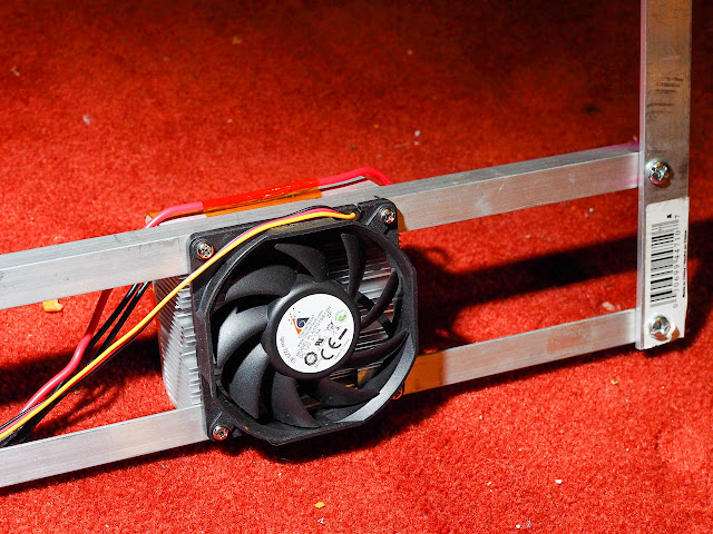
Thermal protection and dimmer circuit: I have been using an inexpensive bimetal thermal switch (thermostat) as the thermal protection against fan failure. Quality CPU fans have been reliable, and they are long lasting. But if it fails, LEDs could overheat and break. The thermal switch is on the top right corner of the heatsink with two black wires coming out, and it is under the orange Kapton tape. I used FUJIK 50ml Silicone Thermal Adhesive (link1, link2) to attach the thermostat onto the heatsink, and covered it with Kapton tape as the insurance. I'm using KSD-9700 50C normally open (NO) switch. Note well that this kind of thermal switch comes in 2 versions; normally open or normally closed. Normally open switches are disconnected, but it makes a connection when the critical temperature is reached. Nomrally close switches do the opposite things.

Here is the wiring diagram of the thermal protection/dimmer control:

One way to dim with 3-in-1 dimming function of a Meanwell driver is to connect a resistor between Dim+ (blue) and Dim- (white) wires of the driver. When the resistance is >100k ohm, it will output 100% current (1400mA). If you don't care about dimming, just don't connect anything (resistance of infinity), and it will output 100% current. As you decrease the resistance, the output current decreases proportionally (down to 10%). So if you connect <10k ohm resistor (or if you directly connect Dim+ to Dim- to give near 0 ohm), it ill be outputting 1400mA * 0.1 = 140mA.
The thermal protection works in the following way. At the normal operating temperature (i.e. heatsink fans operating correctly), 100k ohm potentiometer is used to dim the DC current. But when one of the heat sink overheat, the thermal switch closes, and the total resistance (Rt) becomes Rt = (R1 + R2)/(R1 * R2). If we use about 11k ohm for R2 and set the R1 to full power (100k ohm), then Rt becomes 10k ohm. So soon after the failure of the heatsink fan, all of the light get dimmed to 10% of full output, and all COB LEDs will be protected. I put a 10k ohm resistor for R2, but actually it works without the R2 resistor.
4x CXB3590 installed on the top shelf.

I was curious about the evenness of this set up. So I measured photosynthetic photon flux density (PPFD) in a grid patter at eery 8 inches with Li-Cor Quantum PAR sensor, LI-190 (a link to the newer version of this sensor). The measurement was take at the bottom of the drip tray, so the plant leaves sitting a lot higher will get much more light than this. The height of the light is about 36". The unit is µmol m-2 s-1. Thanks to the reflective tent, it achieves amazingly even/homogenous coverage. There is only slight dip at the very edge of the grow tent.
The bottom shelf has 4 COB LEDs, but they consists of a mixture of several different COB LEDs. So it is a bit more uneven/heterogeneous. But I can use this information to arrange low and high light plants.
Effects of dimming on overall efficiency.
As you reduce the current by the dimmer, efficiency of LEDs goes up. However, the driver efficiency of AC/DC conversion goes down. Some drivers like HLG-185C doesn't suffer too much from lower load, but I was curious how the overall efficiency (including LED and driver efficiency) responds to dimming. I measured the wattage (including LED + driver) with P3 International P4460 Kill A Watt EZ, and measured PPFD at 12" from one CXB3590. I repeated the measurement after increasing the wattage by turning the dimmer dial up. I waited a couple minutes after each time I changed the dimmer to stabilize the temperature. The heatsink fan was running at less than 12V, and each fan was consuming about 1.375W (5.5 W for 4 fans). I used cardboards to block other 3 COBs, so I'm measuring the PPFD of only 1 CXB3590. The following figure shows that overall efficiency goes up slightly with dimming, until you dim too much (below 30% of full power). Note that this curve is specific to this combination. AC/DC efficiency of other drivers could deteriorate more dramatically with dimming. So the conclusion is that dimming in a high quality driver isn't a bad thing.
A disclaimer: I'm just a biologist, who happen to understand a bit of electronics. I'm providing this information just in case it is helpful for someone. With high wattage LEDs, it could be dangerous if you do not use your common sense. So please be careful. If you follow this post, and if something bad happens to you, I'm not responsible for the damage. I generally think "release of liability" clause is silly. But after seeing the results of 2016 US presidential election, I realized the scary reality that there are so many people who can't think critically, check facts, nor use common sense. Please use your brain, and check the correctness of what's written in this blog before you blindly trust everything. There are lots of incorrect and false information on internet (and in politics). I try to be accurate, but if there is incorrect information here, please let me know.
 |
| Caution: this is using 72V version of CXB3590. So this circuit will not work with 36V version. |

I made the frame out of aluminum angles from Lowes, and the emitters are about 90cm (3') apart. The driver is not attached to the frame because the driver stays outside of the grow tent to reduce the heat in the tent. It doesn't become too hot, but it becomes quite warm.

Here is the details of how they were connected to the heatsink. I basically used the fan mounting screws to attache the heatsinks to the frame.

Thermal protection and dimmer circuit: I have been using an inexpensive bimetal thermal switch (thermostat) as the thermal protection against fan failure. Quality CPU fans have been reliable, and they are long lasting. But if it fails, LEDs could overheat and break. The thermal switch is on the top right corner of the heatsink with two black wires coming out, and it is under the orange Kapton tape. I used FUJIK 50ml Silicone Thermal Adhesive (link1, link2) to attach the thermostat onto the heatsink, and covered it with Kapton tape as the insurance. I'm using KSD-9700 50C normally open (NO) switch. Note well that this kind of thermal switch comes in 2 versions; normally open or normally closed. Normally open switches are disconnected, but it makes a connection when the critical temperature is reached. Nomrally close switches do the opposite things.

Here is the wiring diagram of the thermal protection/dimmer control:

One way to dim with 3-in-1 dimming function of a Meanwell driver is to connect a resistor between Dim+ (blue) and Dim- (white) wires of the driver. When the resistance is >100k ohm, it will output 100% current (1400mA). If you don't care about dimming, just don't connect anything (resistance of infinity), and it will output 100% current. As you decrease the resistance, the output current decreases proportionally (down to 10%). So if you connect <10k ohm resistor (or if you directly connect Dim+ to Dim- to give near 0 ohm), it ill be outputting 1400mA * 0.1 = 140mA.
The thermal protection works in the following way. At the normal operating temperature (i.e. heatsink fans operating correctly), 100k ohm potentiometer is used to dim the DC current. But when one of the heat sink overheat, the thermal switch closes, and the total resistance (Rt) becomes Rt = (R1 + R2)/(R1 * R2). If we use about 11k ohm for R2 and set the R1 to full power (100k ohm), then Rt becomes 10k ohm. So soon after the failure of the heatsink fan, all of the light get dimmed to 10% of full output, and all COB LEDs will be protected. I put a 10k ohm resistor for R2, but actually it works without the R2 resistor.
5. Measurement of light coverage homogeneity
This 4x CXB3590 was installed over the top shelf of my 4'x4'x8' grow tent. The bottom shelf is using 4 older COBs (CXA3070, 2x earlier generation Vero 29, and 1 cheap eBay 100W COB). The photo below is right after major cleaning of the grow tent. After 2-3 years of use, algae (actually cyanobacteria) start to grow on the wall, and the reflection gets compromised. This is my largest tent, and it was quite a bit of pain to clean it up. I think I wouldn't get this size tent in the future, a grow tent with 2'x4' foot print is much easier to deal with. Each shelf has a drip tray made out of plywood, and lined with plastic sheets. So water doesn't drip down from the top to bottom shelves.

4x CXB3590 installed on the top shelf.

I was curious about the evenness of this set up. So I measured photosynthetic photon flux density (PPFD) in a grid patter at eery 8 inches with Li-Cor Quantum PAR sensor, LI-190 (a link to the newer version of this sensor). The measurement was take at the bottom of the drip tray, so the plant leaves sitting a lot higher will get much more light than this. The height of the light is about 36". The unit is µmol m-2 s-1. Thanks to the reflective tent, it achieves amazingly even/homogenous coverage. There is only slight dip at the very edge of the grow tent.
 |
| PPFD measurement from 4x CXB3590 (the top shelf) in a reflective grow tent. The light was about 36" above the floor. The approximate coordinates of the four CXB3590's are (x,y) = (6", 8"),(34",8"), (6",32"), and (34", 32"). |
 |
| PPFD measurement of the bottom shelf in a reflective grow tent. The location and the types of four COB LEDs are (x, y, height, type = (10", 12", 32"H, CXA3070 3000K @53.4W), (32",14", 32"H, Vero 29 @82W), (10", 26", 31"H, Cheap eBay 100W COB cool white @47.2W), and (28", 24", 32"H, Vero 29, 59.2W). The wattage is measured with P3 International P4460 Kill A Watt EZ, so it includes electricity wasted by the CC driver. But it does not include the electricity used by the fan on the heatsink. The efficiency of the drivers are slightly below 90%. |
Effects of dimming on overall efficiency.
As you reduce the current by the dimmer, efficiency of LEDs goes up. However, the driver efficiency of AC/DC conversion goes down. Some drivers like HLG-185C doesn't suffer too much from lower load, but I was curious how the overall efficiency (including LED and driver efficiency) responds to dimming. I measured the wattage (including LED + driver) with P3 International P4460 Kill A Watt EZ, and measured PPFD at 12" from one CXB3590. I repeated the measurement after increasing the wattage by turning the dimmer dial up. I waited a couple minutes after each time I changed the dimmer to stabilize the temperature. The heatsink fan was running at less than 12V, and each fan was consuming about 1.375W (5.5 W for 4 fans). I used cardboards to block other 3 COBs, so I'm measuring the PPFD of only 1 CXB3590. The following figure shows that overall efficiency goes up slightly with dimming, until you dim too much (below 30% of full power). Note that this curve is specific to this combination. AC/DC efficiency of other drivers could deteriorate more dramatically with dimming. So the conclusion is that dimming in a high quality driver isn't a bad thing.
 |
| PPFD was measured at 12" from one of CXB3590. The unit of y-axis is µmol m-2 J-1. |
A disclaimer: I'm just a biologist, who happen to understand a bit of electronics. I'm providing this information just in case it is helpful for someone. With high wattage LEDs, it could be dangerous if you do not use your common sense. So please be careful. If you follow this post, and if something bad happens to you, I'm not responsible for the damage. I generally think "release of liability" clause is silly. But after seeing the results of 2016 US presidential election, I realized the scary reality that there are so many people who can't think critically, check facts, nor use common sense. Please use your brain, and check the correctness of what's written in this blog before you blindly trust everything. There are lots of incorrect and false information on internet (and in politics). I try to be accurate, but if there is incorrect information here, please let me know.
Well written and inforamive. Thanks for taking the time!
ReplyDeleteThank you for the comment!
DeleteHi :) So if iI got a 185H-36A driver everything will be fine with 4x cxb3950 parallel connection?
ReplyDeleteI think you are talking about Meanwell HLG-185H-36A, which can go up to 36V. According to Cree PCT, 36V version of CXB3590 should require a little less than 35V at the current (1.3A each). So it will work. You can't use 72V version of CXB3590.
DeleteI haven't checked the recent price, but Bridgelux V22-D might be more economical. It will give slightly lower output (about 10% less) and slightly better efficiency than CXB3590 for a given current. Vf is around 33.3V, so your driver should work.